以下Mile Marker液压汽车绞盘安装由OFF-ROAD.COM提供。
|
FORD
Trucks BBS Project Steps Introduction The Return Outfitter Camper Mile Marker Winch Installation Suspension Mods Custom Fabrication Forged Wheels Exhaust Upgrade Trans Fortification Electronics |
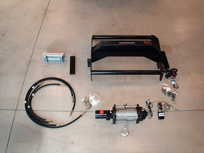
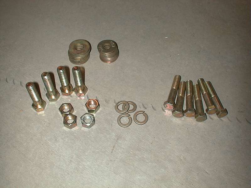
Four Tons of Fun can get you in serious trouble. At 7700lbs. soaking wet, our F-350 is one Big Truck! Getting our butt's out of the proverbial sling while deep in Baja, far from the nearest AAA operator won't happen at the notion of high floatation tires or better than average driving skills. Honestly, in the humble opinion of this off-road veteran, if you plan on venturing off the pavement in a serious way, a vehicle of this size absolutely needs a recovery system capable of pulling the vehicle's GVWR+ out of the nastiest situation. Fortunately for us, the kind folks at MileMarker stepped up to the needs of Project Great White with sponsorship via a full-on, 12,000lb. hydraulic winch system. What? Hydraulic? Yep, unlike the more common, electric winch systems, this unit is powered by a hydraulic motor that derives its power from the power steering pump attached to our mighty PowerStroke Diesel. "So why is this better?" you ask. Well, right of the top of my head, I can envision long duration pulls to be a much more reasonable practice than with an electric unit even while UNDERWATER!. Hydraulic motors have an incredible life cycle. Same with power steering pumps. Can you say the same for an electric motor under severe load? The MileMarker unit is sealed from the elements. Yes, it works underwater as well as above. I don't want to start a debate here, as we'll solve this riddle next month when we cover a 12,000lb winch "Pull Off" between our MileMarker and a very popular electric unit so, let's move on to the installation. Our 70-52000C model, landed on our doorsteps on a mini pallet. The kit included an incredibly stout front bumper and grille guard that acts as a winch mounting platform, numerous hoses, a remote solenoid control valve, hose fittings, nuts, bolts and others items. The net weight of this package is just over 200 lbs. All components are first class. MileMarker seems to have the corner on super tough industrial grade fasteners. Most every item was rated extremely high, including the washers.
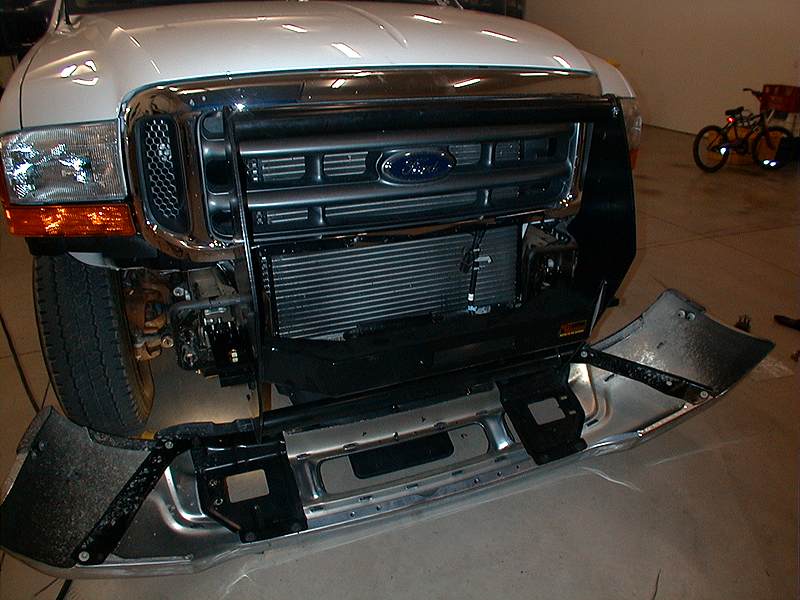
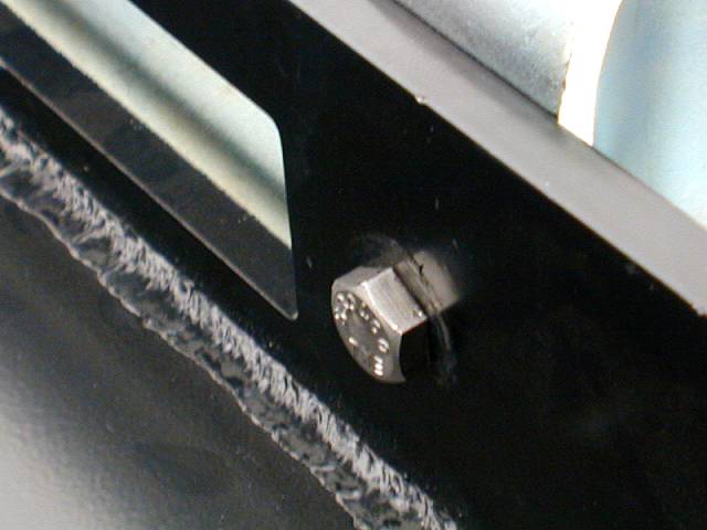
On our F-350, the first order of business involves removing the front bumper and tow hook assembly. Note, that we left the bottom valance apron in place as the limited re-insert, plastic fasteners holding same are best accessed with the bumper laid open from the chassis. An early surprise on our rig was the proliferation of Metric fasteners. Just about every fastener we touched on the mighty Ford was measured in millimeters. Before you start this project on your rig, we strongly advise you to stock up on high quality, metric wrenches and 1/2" drive sockets.
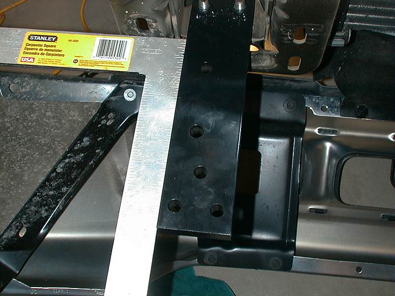
The winch bumper attaches to rails that are fastened to the F-350 frame using the former tow hook mounts. I can't think of a stronger or more accessible point to attach to the chassis. Now, I'm are pretty "anal" about details and I wanted to make sure that the installation was perfect. So, I puckered up and proceeded with the details.
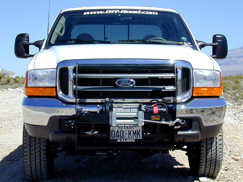
Wow! The F-350 is already intimidating. With this extra steel up front, even the most brave, road rager will steer clear when we enter traffic.
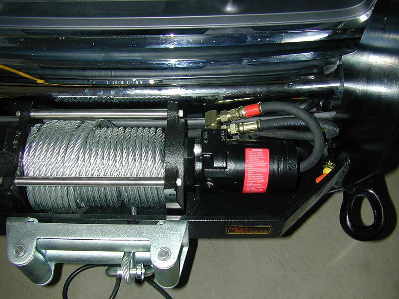
With the bumper firmly in-place, the next order of business is the placement of the winch mechanism and motor. And here folks, we find a few problems and present rules to remember on assembly. Trick #1. Do not use washers on the inside of the fairlead bolts. The winch mechanism sits so close to the front of the mount that washers will raise the exposure of the head bolts and misalign the mounting holes for the winch.
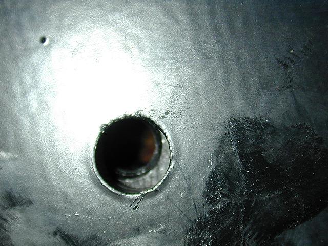
Remember ol' Norm? We had him grow a third hand because it takes five to lower the winch onto the bumper and guide the coiled winch cable in place through the fairlead. Trick #2. Anchor the cable outside the fairlead at first opportunity. Fasten the winch assembly to the bumper. DOH!! The mounting holes do not line up! No problem, a stout drill, a slightly oversize drill bit and a liberal amount of cutting oil will open the hole to provide alignment. What'ya bet, that MileMarker has this fixed on your install?
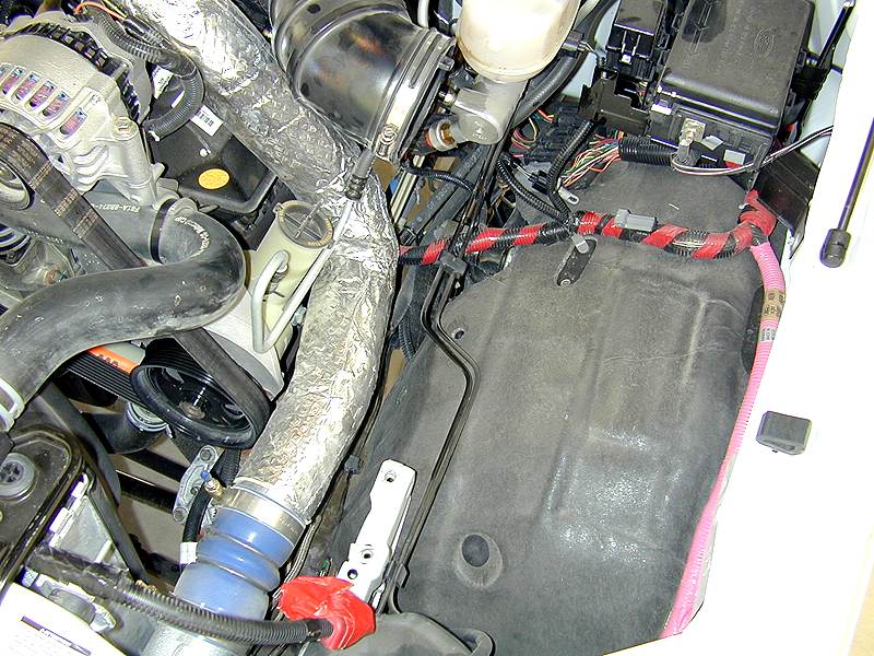
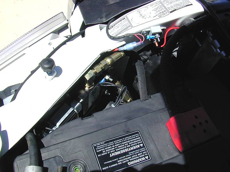
All the heavy lifting is done and it's time for technical craftsmanship. The trick at this step of the project is locating the proper mounting point for the control solenoid. The F-350 engine compartment is complex and crowded. The front of the truck is a very efficient airdamn that offers little in the way of passages for routing the hydraulic hoses. To get the proper access as well as a perspective of the best control valve mounting points, we removed the large plastic tray assembly for the air filter system, snorkel and second battery. Do not be intimidated, this entire assembly is attached by no more than 8 bolts. Once out of the way, even a ham handed guy like myself can squeeze grapplers into the many tight space areas to perform the job.
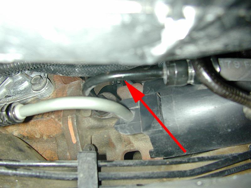
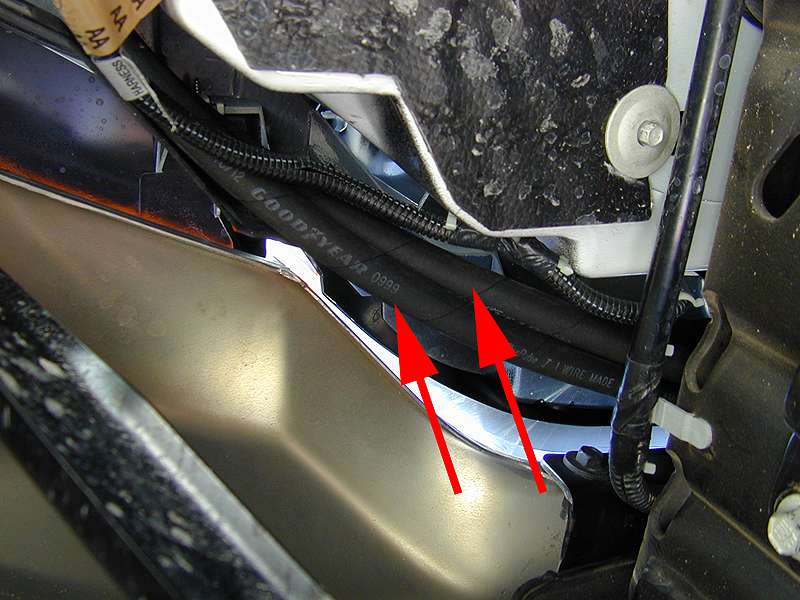
Four hydraulic hoses are included with the milemarker kit. Two hoses run from the winch motor to the valve, and two from the valve to the vehicle's power steering system. Since our rig is Diesel Powered, the power steering pump also serves as a boost mechanism to the vehicle's brakes. This is commonly called a "Hydraboost System". MileMarker places the solenoid control valves into the vehicles power steering system, between the hydraboost mechanism and the steering box. Attach the new hose to the steering box leaving the fasteners loose. Note: it is almost impossible to avoid a power steering fluid spill at this step. Insure, that you have a drip pan in place to protect the garage floor as well as the endangered, spotted, ring-nosed, hermaphrodite whale that may be affected if the demon, fluid spill finds itself mysteriously into the gutter, then the flood control system and on to the ocean via transcontinental river system. Most of all, watch out for the Green Police!
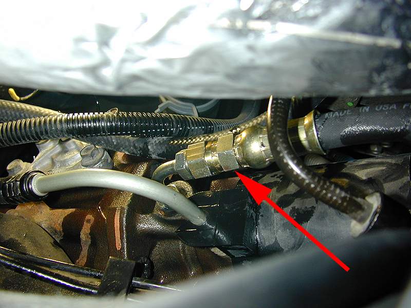
Disconnect the same factory hose at the Hydraboost system and attach the other hose from the control valve. Leave the fittings loose.
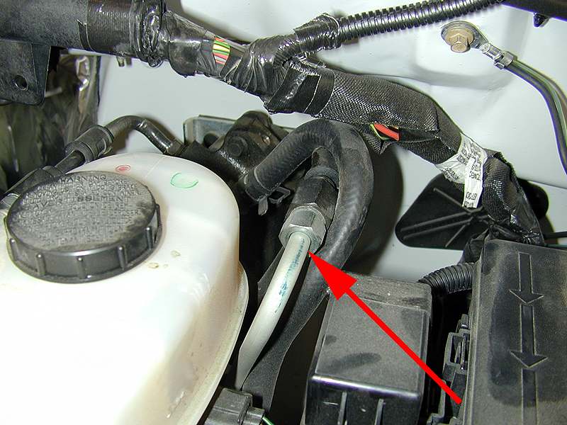
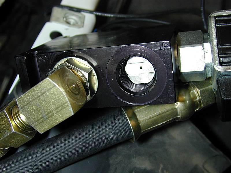
Make sure that the Freewheel Orifice Checkplate is placed in the control valve behind the hose that is fastened to the top port of the winch motor. With all lines routed and installed, wiggle the control valve into the most optimum mounting position. Test-fit the battery and airbox tray back to insure that proper clearances between all points are available. Once you are satisfied, permanently fasten the control valve mounting plate and valve assembly.
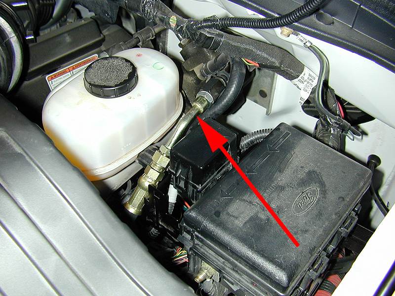
Torque all hose fittings per spec. Reinstall the battery and airbox tray and refill the power steering pump reservoir. It goes without saying, that all hydraulic hose runs should avoid sharp metal and plastic abrasion points. Yes, even plastic can wear through a stout rubber hose when pressure is applied at the right angle. As an extra step, we will return to our installation after putting a few hundred miles on our vehicle to make sure that hoses have not settled into dangerous positions. If they have, we will use top quality, rubber insulated hose mounting clamps to pull the hoses into protected locations. We'll cover this step along with the wireless system installation next month. Stay tuned.
Electrical connections for the MileMarker hydraulic winch system are extremely simple. Quality connectors, wire and zip ties are provided. Use them! We chose to mount our hand control receptacle up front on the bumper. A quick trip to the Trailer Supply store offered the proper size and color in mount. We used surplus, stainless fasteners from the winch kit to make this part of the install "AR Tech, perfect".
Follow the instructions on bleeding air from your power steering system. Clean up your mess and you're finished. Once we have proven the system to be leak free as it appears, we will flush the entire power steering system to insure that we have a common fluid base with all possible contaminants purged.
What's next? Enjoyment of a cold beer and a comfortable chair in the semi-well lit yet, plush garage at ORC headquarters. Seriously, we will place our MileMarker Winch System against a well known electric winch of the same capacity on a similar truck platform for the first ever, "Off-Road.com Winch Pull Off". The folks at MileMarker seem to be extremely confident. In early conversation, with a snicker in their voice, they insured me that they would pay for any damages on the electric winch vehicle. I I think their confidence is well grounded. My guess is that the electric unit will become a smoking heap of ozone spewing wires and insulation. We shall see for sure. Stay tuned!
|
||||||||||||||||||||||||||||||||||||||||||||||||||||||||||||||||||||||||||||||||||||||||||||||||||||||||||||||||||||||
无忧汽车绞盘网 摘编提供 关闭本页